On June 21, at the 2025 SMM (4th) Electric Drive System Conference & Drive Motor Industry Forum - Automotive Electric Drive System Forum, jointly hosted by SMM Information & Technology Co., Ltd., Hunan Hongwang New Material Technology Co., Ltd., Louxing District People's Government, and the National-level Loudi Economic and Technological Development Zone, Jia Yuqi, the Deputy Dean of the Zhejiang Electric Drive Innovation Center Research Institute, shared insights on "Design Characteristics of Drive Motors in the Context of High Voltage and High Frequency."
Background and Challenges
1.1 Background - Policy/Industry
The speed range of electric vehicle (EV) drive motors is wide, and they require frequent acceleration and deceleration during driving, making the operating conditions much more complex than those of general speed control systems. The electric drive system is crucial in determining the dynamic performance of EVs.
• US Department of Energy (DOE) 2025 EV Development Plan;
• Growing consumer demand for driving range and performance;
• Best practices of local automotive brands in "overtaking on curves" in the global automotive industry;
• An important approach to achieving "low-carbon environmental protection, carbon peak, carbon neutrality, energy conservation, and emission reduction";
This requires electric drive systems to be lighter, more compact, more efficient, and more reliable, with increasing demands for power density.
1.1 Background - Electric Drive System Solutions/Components and Windings
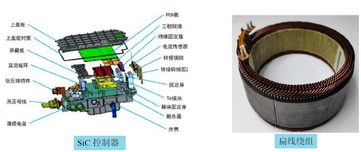
SiC inverters offer high switching frequencies, low losses, and high working voltages, contributing to increased drive motor speed and power density;
Flat wire windings have high slot fill factors, low DC resistance, and good thermal conductivity, enhancing motor efficiency and power density under medium-to-low speed operating conditions;
1.1 Background - Electric Drive System Solutions
Mainstream solutions for electric drive systems in new energy vehicles: SiC inverter + flat wire wound permanent magnet synchronous motor;
1.2 Technical Difficulties and Challenges - High Voltage, High Frequency
High voltage leads to increased dielectric losses in insulating materials and a higher risk of partial discharge;
High frequency results in increased AC losses in flat wire windings and uneven distribution of losses within the slots, which can easily lead to local hot spots;
Under high voltage and high frequency conditions, the uneven distribution of turn-to-turn voltage in the windings is exacerbated by high-frequency parasitic parameters, causing insulation damage and failure;
1.2 Technical Difficulties and Challenges - Countermeasures
Thoroughly consider the uneven distribution of losses, heat, and voltage stress during the early design stage;
Use high-temperature-resistant, high-corona-resistant insulating varnish, insulating materials, and enamelled wire;
Comprehensive countermeasures should be taken from multiple aspects, including new motor topologies, new winding structures, new materials, new processes, and efficient thermal management systems;
Key Considerations in Drive Motor Design under High Voltage Conditions
2 Key Considerations in Drive Motor Design under High Voltage Conditions
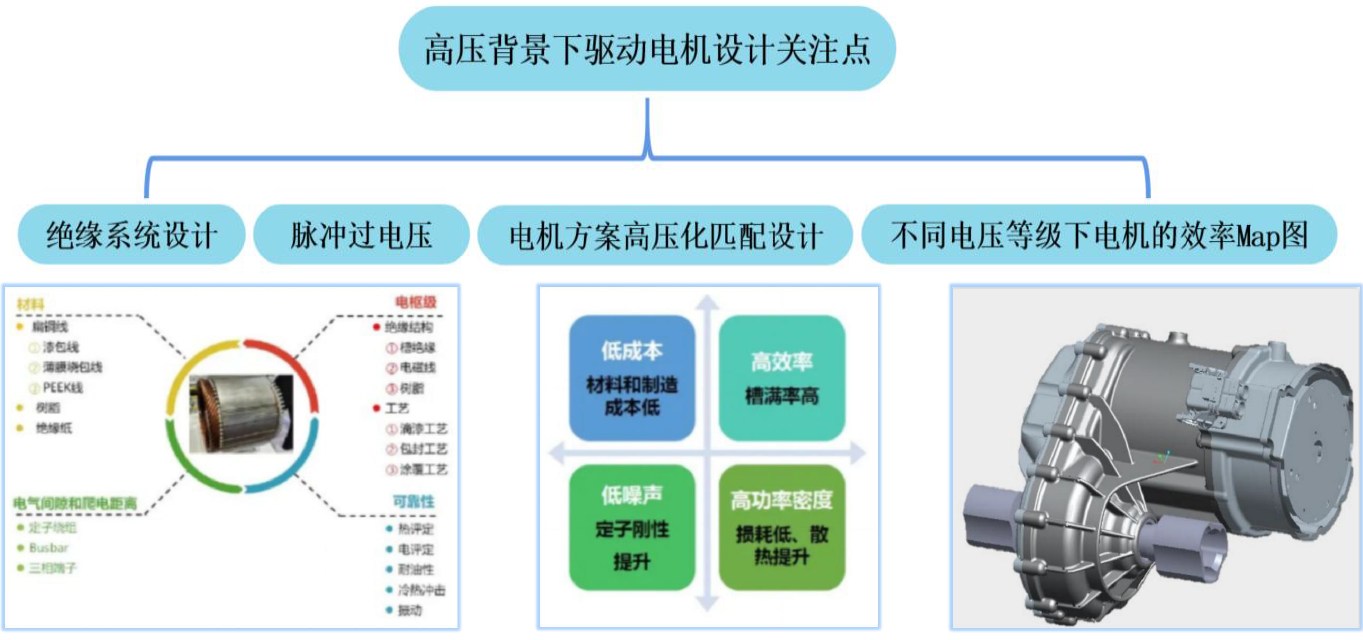
2.1 Insulation System Design - Materials
Under high-frequency and high dv/dt excitation, the winding insulation will be subjected to the dual effects of significant electrical and thermal stresses. Given the demands for high power density and high reliability, the insulation safety margin of the motor gradually approaches the allowable limits of material parameters. Therefore, it is necessary to conduct safety analysis and assessment of turn-to-turn insulation in motors during the initial design stage. To ensure insulation safety margins and avoid damage and premature failure, measures such as increasing insulation thickness, using insulation materials with higher temperature resistance ratings, and corona-resistant insulation materials can be taken to ensure insulation safety. For example, the corona-resistant PEEK wire developed by Furukawa Electric in Japan and used in Honda's iMMD drive motor can achieve higher Partial Discharge Inception Voltage (PDIV) and better thermal conductivity.
2.1 Insulation System Design - Cooling
As the power density of the motor increases, the loss density inevitably increases as well. Coupled with the effects of proximity and skin effects under high-frequency conditions, this can easily lead to uneven heat source distribution within the motor slots, resulting in localized overheating.
The lifespan of motor insulation materials is closely related to temperature. Therefore, attention should be paid to the motor's thermal management plan, and the development of efficient cooling structures, such as in-slot winding cooling and direct winding cooling, should be strengthened.
2.2 Pulse Overvoltage - Causes and Calculation Models
Due to the mismatch in characteristic impedance among the inverter, transmission cables, and motor, according to the wave reflection principle, PWM pulse waves will be reflected multiple times between the inverter and motor windings. The superposition of reflected and incident voltages will generate pulse oscillation voltages at the motor winding ends that are higher or lower than the bus voltage, thereby generating pulse voltages. The peak voltage is the most dangerous factor causing partial discharge in motor insulation.
2.2 Pulse Overvoltage - Suppression Methods
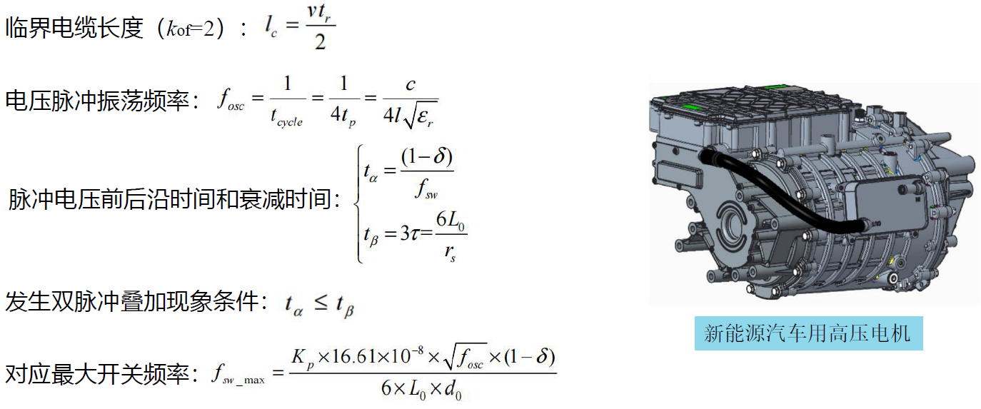
When the switching frequency is lower than this value, the phenomenon of double-pulse superposition will not occur. Therefore, impedance matching design is required to ensure that the switching frequency is lower than this frequency.
2.3 Efficiency Map of Motors at Different Voltage Levels
A comparison was made of the efficiency distribution of drive motors at bus voltages of 400V, 600V, and 800V. As the bus voltage increases, the area of the high-efficiency region of the drive motor significantly expands. Additionally, with an increase in the corner speed, the high-efficiency region shows a clear trend of shifting towards the high-speed region, which matches the demand for high-speed motor design. Therefore, the development of high-voltage electric drive systems for new energy vehicles not only meets the fast charging requirements of batteries but also brings new opportunities for the high-efficiency and high-density design of drive motors.
Key Considerations in Drive Motor Design under High-Frequency Conditions
3.1 Current Harmonic Losses - Causes and Hazards
Drive motors for new energy vehicles are typically driven by voltage source inverters using Space Vector Pulse Width Modulation (SVPWM) technology. During the continuous switching on and off of each device in the switching cycle, high-frequency current harmonics are generated. Meanwhile, the dead time and turn-on/turn-off times of the devices can cause distortion in the inverter's output voltage and current waveforms, thereby introducing high-frequency harmonics. These voltage and current harmonics are typically located near the carrier frequency and its multiples, increasing losses and reducing efficiency.
3.1 Current Harmonic Losses - Suppression Methods
As the switching frequency increases, the sinusoidal degree of the current waveform improves, and the frequency of the main sub-harmonics increases, but the amplitude of the harmonic currents significantly decreases.
Therefore, the suppression method for current harmonic losses is to enhance the sinusoidal degree of the current waveform, reduce the harmonic content of each order, and thereby reduce current harmonic losses. The main measures include increasing the inverter switching frequency, skewing slots/poles, optimizing the magnetic pole structure, selecting the winding form, and selecting the slot-pole combination, among others.
3.2 High-Frequency AC Losses in Windings - Causes and Hazards
When alternating current flows through a conductor or when it is placed in an alternating magnetic field, eddy current effects, namely skin effect and proximity effect, are induced. The skin effect causes the current to tend towards the surface of the conductor when alternating current flows through it, while the proximity effect causes the current in two adjacent conductors to tend towards the sides due to the influence of each other's magnetic fields. Both effects reduce the actual conductive area of the conductor and increase losses.
The higher the operating frequency of the drive motor, the more severe the AC losses in the flat wire windings. Moreover, drive motors for new energy vehicles operate under various conditions, and at certain operating points, the proportion of AC losses in flat wire windings is very high. The adverse impacts are mainly in three aspects: reduced motor efficiency, which is not conducive to improving the power density of the electric drive system; increased heat dissipation requirements, which impose higher demands on the motor cooling structure and thermal management; and uneven distribution of losses within the slots, leading to local hot spots and threatening the insulation safety of the motor.
Therefore, sufficient attention must be paid during the motor development stage.
3.2 High-Frequency AC Losses in Windings - Suppression Methods
The suppression methods for AC losses in flat wire windings at high frequencies mainly include:
Increasing the size of the stator slot opening (to reduce conductor losses caused by the armature magnetic field);
Increasing the distance between the conductor and the stator slot opening (to reduce conductor losses caused by the leakage magnetic field in the slot under the permanent magnet magnetic field);
Reducing the conductor size (to weaken the effects of skin effect and proximity effect);
Appropriately increasing the size of the magnetic isolation bridge;
Transposing conductors between slots and layers (to reduce circulating current losses when the number of parallel branches is greater than one);
Using Litz wire for the windings (inter-strand transposition).
3.3 Motor Efficiency at Different Switching Frequencies
A comparison was made of the losses in drive motors at switching frequencies of 10 kHz, 20 kHz, and 50 kHz. As the switching frequency increases, the losses in each part of the motor show a decreasing trend. However, when the switching frequency increases to a certain value, the motor losses will no longer change significantly. Therefore, within a certain range, a higher switching frequency is beneficial for reducing overall motor losses, which also facilitates high-speed motor design.
However, as the switching frequency increases, inverter losses will correspondingly rise. Consequently, the selection of switching frequency requires balancing motor and inverter losses to achieve the lowest total losses in the entire electric drive system.
Summary
4.1 Requirements
Core design requirements for drive motors under high-voltage and high-frequency conditions:
Ø Reliable insulation: High-frequency PWM pulses reflect multiple times between the inverter and motor windings, causing voltage superposition at the winding ends and posing a threat to winding insulation safety;
Ø Electromagnetic efficiency: High-frequency operation exacerbates skin effects and harmonic losses, necessitating precise electromagnetic modeling to optimize flat copper wire winding topology, slot opening structure, and magnetic barrier design, employing multiple methods to comprehensively improve electromagnetic conversion efficiency;
Ø Effective cooling: High power density leads to concentrated losses and rising thermal energy density. Technologies such as 3D-printed cooling channels and in-slot water cooling can be combined to establish a multi-channel cooling system, utilizing fluid and thermal field coupling simulations to optimize cooling paths and maintain motor component temperatures within reasonable ranges.
4.2 Contradictions
• Increasing the supply voltage significantly expands the high-efficiency zone of the drive motor, but the high dv/dt pulse voltage output by SiC simultaneously increases the insulation voltage stress on motor windings, threatening winding insulation safety;
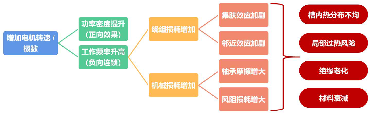
• Higher operating frequencies facilitate increased rotational speed and pole count, as well as improved drive motor power density, meeting system demands for miniaturization and lightweight design. However, this also leads to increased AC winding losses and mechanical losses, with the former exacerbating uneven thermal distribution within slots.
4.3 Balance
• As a multi-variable, strongly coupled, and nonlinear system, solving one technical issue in motor design inevitably introduces another. Motor design is a process of seeking balance amid contradictions, requiring trade-offs between performance enhancement, loss suppression, cooling structure, thermal management, and insulation safety;
• Moving beyond the inertia of single-product thinking to consider problems more macroscopically, from improving the entire electric drive system to enhancing overall vehicle efficiency and power density.
Additionally, it introduced the overview, positioning, construction goals, strategic plans, humanoid robot, and low-altitude economy of the Zhejiang Electric Drive Innovation Center.
》Click to view the 2025 SMM (4th) Electric Drive System Conference & Drive Motor Industry Forum Special Report